Control System Of Turbine - Failure & Maintenance

Team Minimac
Feb 24, 2022 · 2 min read


Control System
The turbine control system describes the control over the opening of control valves corresponding to demand signals, and steam flows into the turbine with the help of a governing system that facilitates the operation of the turbo set in an interconnected grid system.
Governing system is responsible for various function such as speed & load control functions, the start-up/shut-down controls, the over-speed control, turbine stress calculation, to control the initial run-up and synchronization of the Unit, to assists in matching the power generated to that demanded by responding to system frequency changes, to regulate the steam control valves position (and hence the load generated)in response to signal from the operator or from the load dispatch Centre, to restrict the speed rise within acceptable limits should the unit get disconnected (islanding) from the lgridoad and some protective trip functions.
With continuous research and developments in modern turbine technology, the following three types of governing system are mainly available nowadays in power plants:
1. Hydraulic: Hydraulic governors have only a speed controller loop. Machine speed is measured and indicated as a primary oil measure. Speed transducer is a centrifugal pump whose discharge pressure is a function of machine speed. This signal is sent to a hydraulic converter, to generate a high-power hydraulic signal for the operation of different control valves. The range of speed control is 2790-3210 rpm. Its speed regulation range (droop)is 7%. HG (typically) cannot be isolated mechanically like EHG.
2. Electrohydraulic: This consists of three control loop speed, load, and pressure. Speed Electronic Transducer is used for measuring the machine speed. This signal is processed electronically and then sent to an Electrohydraulic converter (E-H) for converting the electronic signals into proportional hydraulic signals (I-P converter) for the operation of control valves. It gives a faster response and precise frequency control. The range of speed control is wider (0 – 3210 rpm). Its speed regulation(droop) is 5%.EHG can be mechanically isolated by closing the secondary oil line from the local.
Major devices/component of the above Governing system are:
- Remote trip solenoid
- Turbine trip gear (main trip valve)
- Starting and load limiting devices
- Speeder gear
- Auxiliary follow-up piston
- Follow up piston
- Hydraulic amplifier
- Electro-Hydraulic convertor
- Sequence trimming device
- Solenoid for load shedding relay
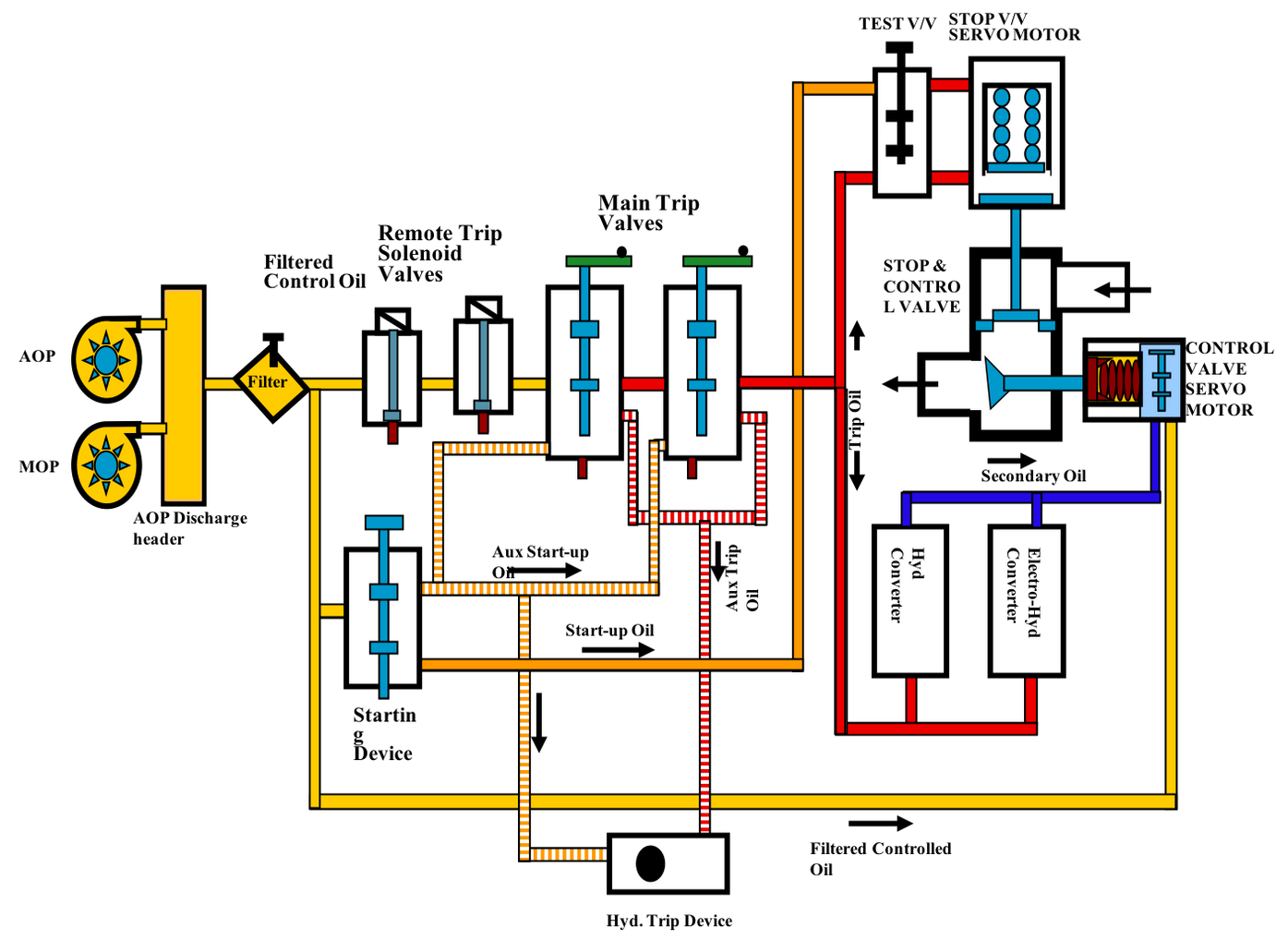
Block Diagram of EH Governing system
Follow our page and stay updated about Lubrication Reliability - Minimac Systems Pvt Ltd
Oil Lube Flow In The Circuit:
- Control Oil: Oil is taken from the AOP/MOP discharge header for the governing system.
- Trip/Aux Trip Oil: These two oil circuits are established through main trip valves under reset condition.
- Start-Up/Aux Start-Up Oil: These two oil circuits are established to peak pressure through starting device at 0% position and pressure started reducing when the position of the starting device is raised.
- Aux Secondary Oil: This oil circuit is the output of the hydraulic governor and input to the hydraulic converter.
- Secondary Oil: Output to Hydraulic and Electrohydraulic converter.
- Test Oil: This oil circuit is established to test over speed trip device when the turbine is running at rated speed.
- Remote trip Solenoid Valves: These are two in nos. and when any turbine trip gets initiated, the solenoids get energized& control oil gets drained through the valves and trips the MTV.
- Main Trip Valve: These are two in nos. and called the main trip gear. All the turbine tripping take place through this device under non-trip condition establishes trip & aux trip oil and used for resetting/opening the stop valves and producing HP/IP secondary oil.
- Starting device: this device is used for resetting and opening the stop valves and, main trip valves &hydraulic trip devices. this device either be operated manually by handwheel or from remote (MCR) through a motorized actuator.
- Speeder gear: This device in combination with starting device forms a hydraulic governor and provides an input hydraulic signal to the hydraulic converter. this device either be operated manually by hand wheel or from remote (MCR) through a motorized actuator.
- Hydraulic/Electro-hydraulic converter: amplifies & converts hydraulic /electrical signals to hydraulic signals (HP/IP secondary oil) for the operation of the HP/IP control valve.
- Hydraulic trip devices: These devices provide mandatory protections of the turbine by draining aux trip oil. these devices are reset by aux start-up oil.
3.Digital Electrohydraulic: The main function of the DEH control system is to control before starting up (auto judging very hot, hot, warm or cold state), auto-adjusting servo system static relation, turbine latching, speed and load control, protection, supervising and communication. It consists of electronic parts and EH system which controls the speed/load through controlling the openness of all valves. The feature of special controlling on IP start-up mode (HP casing switchover and isolating of HP casing) can perform quick start-up and stable running for a long time with low load at all phases.
This is a modern high-pressure (110 to 180 bar) governing system.
Let’s know how it works. The electrical measuring and processing of signals offer advantages such as flexibility, dynamic stability and simple representation of the complicated functional relationship. The processed electrical signal is introduced at a suitable point in the hydraulic circuit through the electro-hydraulic converter. The hydraulic controls provide the advantages of continuous control of large positioning forces for control valves. The integration of electrical and hydraulic system offers the following advantages:
- Exact load frequency droop with high sensitivity
- Reliable operation in case of isolation from power grids
- Dependable control during load rejection
- Low transient and low steady-state speed deviations under all operational conditions
- Excellent operational reliability and dependability
- Safe operation of the turbo-set in conjunction with the Turbine Stress Evaluator (TSE)/Controller (TSC)
Operating Method Of DEH Governing:
- The stop valve for HP/IP will open by the HP fire-resistant oil when the dump valve is closed
- The dump valve will close when the trip oil is under pressure
- The trip oil is under pressure when the trip solenoid (5,6,7,8 YV placed on the trip block) valve is in a de-energized position and the HP Trip oil header is under pressure
- The oil will enter the bottom of the piston through the isolating valve (Supply sol.). Thus, the stop valve opens slowly against the spring force.
- In case of a trip, the trip solenoid valves are energized and AST valves de-energize and HP trip oil header is de-pressurized and thus dump valve open to connect the bottom and top ports to drain the oil to LP accumulators
- The valve quickly closes due to spring force
- After the unit is reset and HP trip oil is formed
- The trip solenoid valve is de-energized conditions will give pressurized oil to the dump valve to keep it closed
- Pressurized Oil is up to the EH servo valve
- The EH Servo valve based on the DEH valve command signal and valve position feedback signal from LVDT will connect the HP Fire resistant oil to the lower part of the piston or lower port to the drain till the matching is achieved
- In the case of Trip, the dump valve opens due to energization of the trip solenoid or depressurization of the HP trip fluid header. The dump valve opening leads to the control valve quick closing due to spring force.
Access more articles, join our network! Click Here
Type Of Control System Loops:
The EHG function consists of mainly following control loops:
1.Speed control loop: In this loop, the speed controller essentially compares the speed reference generated by the speed reference limiter circuit and the actual speed of the turbine and accordingly provides an output for the valve lift controller. This loop only determines the control valve position to adjust turbine speed at setting value before the generator is paralleled to the power system. 2.Power control loop: The task performed in the speed control loop is then transferred to the power control loop or the MSP control loop after synchronization with the system. The steam turbine shall be controlled on this MW-control mode normally. In the event of a drop of grid frequency, the governor valves shall open instantaneously to provide frequency support in the form of additional MW. When the main steam pressure (MSP) control mode is an operation, this MW-controller is tracking to the main steam pressure (MSP) controller. 3.Turbine inlet steam pressure (MSP) control loop: MSP mode (Turbine Follow mode) of operation results in the governing system modulating the steam flow to regulate the steam pressure at a fixed value. The control system shall switch automatically to this mode when faults occur which prevent normal control of the boiler. MSP mode will take over following a drop-in steam pressure of 10% or an increase in pressure of 3%. It shall be possible to manually switch to this mode. When the power control mode is an operation, this steam pressure controller is tracking to the power controller. 4.Steam pressure Limiter control loop: The pressure limiter shall override the governor and progressively reduce the steam flow to the turbine as the steam pressure before the HP steam turbine governing valves drops below a predetermined value in order to limit serve drops in steam temperature. 5.Condenser Vacuum Limiter control loop: This limiting controller shall override the governor and progressively reduce the steam flow to the turbine as the condenser vacuum falls over a predetermined range in an effort to maintain the condenser vacuum at this value. The setting shall be adjustable. It shall be possible to override the device during vacuum raising and it shall not come into operation below 1000 rpm. 6.Control valve (CV) position control loop: An output from the above loops is given to the CV position control loop as its setting. Consequently, it adjusts the CV position in accordance with its characteristic curves respectively. This portion outputs the opening command to the Electro-hydraulic (E/H) converter mounted on each CV separately. Due to each E/H converter having two magnet coils, two separate signal (±10V) lines are connected to them.
Valve Comprised In The EHG Circuit:
Turbine speed control, load control, load shedding relay control and emergency control are carried out by open and close action of each:
- Main Steam Stop Valve (MSSV)
- Main Steam Control Valve (MSCV)
- Reheat Steam Stop Valve (RSSV)
- Reheat Steam Control Valve (RSCV)
Most of the failure-to-trip conditions can be attributed to five basic problems.
- Steam deposits on the valve stem (or stems)
- Lubrication deposits (i.e., soaps, dirt, detergents, etc.) in the top works of the valve exposed to the elements
- Mechanical failures of the valve resulting from bent stems, either in the valve proper or the upper works, damaged split couplings, etc., all within about a 6" area near the centre of the valve mechanism
- Galling of the piston in the hydraulic latch cylinder
- Jamming of the screw spindle in the larger cylinder-type valve design due to forcing by operations personnel
Connect with our experts for Oil Analysis & Condition Monitoring - Click Here
Servo And Proportional Control Valves:
Failures of control valves have resulted in a very expensive loss of production and downtime to many energy generation companies. This led to the increasing use of servo and proportional control valves in modern hydraulic control systems. These devices are inherently at the critical stage of controlling the generating process and quality of the end product.
The most critical factor of their failures is the contamination of the hydraulic fluid with regard to cleanliness and chemical composition like water content and various forms of break down that can occur due to chemical contamination, excessive heat or working of the fluid, inappropriate filters for the valve etc.
To achieve high reliability and asset life for a longer time, it is important to closely evaluate the design of filtration and its effects, components included and circuit layout to achieve the optimum solution. The key system elements are Servo valves and proportional valves, Pumps and motors and Ancillary valves and components.
The types of failure on the basis of contamination can be broadly classified into:
-
Short term failure: This type of failure comes with no warning which
results in an unplanned shutdown of the plant, catastrophic for equipment, production loss.
The main causes are jamming of the spool or plugging of the orifice.
- Particle Jamming: In this mechanism, contaminant gets lodge in the fine clearances between the spool and body, the particles became wedged in the spool blocking control orifices to cause a ‘hard over’ condition or loss of control pressure. To solve this type of problems by filtration, the size of clearances and driving forces to overcome particles should be considered. This causes permanent damage to control lands of the valve which means expensive repair or replacement with a new one
- Silting: Silting refer to a phenomenon where a spool is being held in a fixed position with high pressure across the lands which results in a gradual build-up of fine ‘silt’ particles that can lock the spool within 5-10 minutes. poppet type solenoid valves are used in safety circuits where long stand times can be involved. A conventional solenoid (or the return spring) will not move the spool after 3-5 minutes
- Long term failure: This type of failure directly impacts system accuracy and repeatability. It results from the gradual build-up of other ‘varnish’ or silt type contaminant that degrades the control qualities of the valve such as threshold and hysteresis, wear/erosion of valve parts. Long term effects cannot be eliminated, however, by proper design, it is possible to maximise the useful life of the valve before service or repair is required. This requires the effective application of silt level filtration.
Valve Design:
Control system performance, the filtration requirements and likely contamination sensitivity are dependent on how the best valve design is selected. Design goals should be balanced with component details, component costs and overall system costs. A good understanding of how and why the valve works will provide maximum benefits to the overall design solution. There are three principal areas to be considered for the best designing of a valve:
- Internal forces: Understanding the forces within the valve that provide for correct operation and those that resist operation, is most valuable for understanding optimal filtration requirements. Forces determine both short term and long-term performance for contamination sensitivity and threshold/resolution.
-
Spool position control: For both servo valves and proportional valves the
spool is capable of being positioned anywhere over its total designed stroke. How the spool
is moved and held in that position will have a direct influence on the cost of manufacture,
system accuracy and contamination sensitivity. Three methods used are
- Open-loop or non-feedback
- Mechanical feedback (MFB)
- Electrical feedback (EFB)
-
Design tolerances: Finer tolerances will be more susceptible to wear and
the potential for particle jamming. They will be an important factor for the evaluation of
either servo valves or proportional valves with regard to filtration design. For both short
and long term functionalities below are few manufacturing objectives such as:
- Nozzle diameters and exit clearances
- Spool diametral clearance
- Spool travel - from 0.250mm for high-performance servo valves to 5-10mm for proportional valves. A shorter stroke means faster response, but finer manufacturing tolerances.
- Spool control land overlap - which ranges from 10-20% overlap proportional valves to ‘axis cut’ (zero overlaps) servo valves which require special protection of the lands to maintain performance. Zero overlap valves are used in the pilot section of some proportional valves so that protection requirements can be similar for parts of servo valves and proportional valves.
Control Oil - Fire Resistant Fluid (FRF):
A fire-resistant control fluid (FRF) is used in control and governing systems. The use of fire-resistant control fluid for turbine control and protection systems reduces the risk of fire. This is due to the higher ignition temperature (compared to mineral oil) in case of leaks.
- It shall not cause corrosion to Steel, Copper and its alloys, Zinc, Tin or Aluminium (compatibility to be checked)
- It shall be continuously regenerated with Fuller’s earth, ICB resins or an equivalent regeneration agent
- It must not cause any erosion or corrosion on the edges of the control elements
- It must be shear-stable. It should not contain any viscosity index improver
- FRF leaking from the system, if any, must not ignite or burn in contact with hot surfaces (up to 550 degrees C)
- It must be capable of withstanding continuous operating temperatures of 75 °C without physical or chemical degradation
- It must be miscible with traces (max. 3 % by vol.) of TXP of another brand (without deterioration)
- The air release of the FRF should not deteriorate in presence of Fluoroelastomer seals and packing used in the FRF system
- It must be free of ortho-cresol compounds
- It must not pose a safety or health hazard to the persons working with it, provided that the requisite hygiene regulations are observed
Contamination In FRF/Degradation Of Phosphate Ester
Though Phosphate ester fluid is designed for the long life of service of around 20 years if maintained properly, However, contamination or abuse in the oil because of poorly lubrication practices can degrade the oil life and reliability of the machine. Fluid degradation results in sticking valves, eroded servo valves, plugged filters and/or blocked servo valve strainers. The major contaminant or factor of oil degradation are described below:
Water Contamination
This is the most common and dangerous contaminant which frequently dictates the service life of
FRF fluid. Phosphate ester has the tendency to hydrolyze which means breaking down into acid and
alcohol and this process accelerates with increasing temperature and is catalyzed by the
presence of strong acids and some metals.
Acid formation
Uncontrolled generation of acidic products is harmful to the life and performance of phosphate
esters. strong acids are also chemically reactive and can form metal soaps or salts which
adversely affect foaming and volume resistivity, the latter being used to assess the potential
for servo-valve erosion. This soaps precipitates in servo valves and cause stickiness.
Lowering of Resistivity
Resistivity is a critical performance indicator for phosphate ester fluid quality. Low
resistivity values are associated with electrokinetic wear, a very common failure mechanism of
servo (MOOG) valves.
Solid Contamination
This particulate contamination is responsible for fluid darkening and is generally produced from
micro-dieseling, which is a type of high-temperature fluid breakdown caused by air release
issues. Solid contaminants of more than (>4) micron are measured by ISO4460 but less than (4)
microns are not being detected. On investigation, 90% of total solid contamination in EHC
fluids is below 4 microns which results in plugged filters, blocked servo valve strainers.
Oxidation degradation
Oxidation the most dangerous process which occurs due to contamination gives output in the form
of heat. Oxidative degradation results in the production of a range of strong and weak acids and
from very low molecular weight hydrocarbons that may plate out as varnish to higher molecular
weight hydrocarbons or polyphosphates present as sludge that can increase fluid viscosity and
reduce resistivity while blocking filters and causing valve sticking. External sources such as a
steam line, hot/molten metal or a welding torch located close to the hydraulic line provide heat
to the fluid. The difference between internal ‘hot spots’ is that it occurs when the fluid is in
circulation (except for the fluid being heated up in the tank) and external heat sources occur
when the fluid is static.
Aeration (Thermal Stability and Pyrolysis)
The presence of a small amount of dissolved oxygen will result in degradation at lower
temperatures - particularly in the presence of metals - and apparent changes in the
physical/chemical properties of the fluid may be due to oxidation rather than pure thermal
breakdown.
Maintenance Of FRF Fluid:
The fluid is pressurized, subjected to elevated temperatures, flows through fine clearances and
is exposed to contaminants including water, dirt and air. Its maintenance should be focused on
Keeping the fluid dry, clean and purified, checking material compatibility issues and employ
regular fluid condition monitoring, following the guidelines for handling control fluid and for
treatment of control fluid systems, Preservative Agents in Control Fluid System, precautions to
Ensure Compatibility of the Control Fluid with other Materials, the procedure for sampling and
analysis programs. Below is a chart summing up the maintenance properties:
Purification:
Ion Exchange System
Ion exchange resins have become a preferred form of treatment for fire-resistant fluids used in
EHC systems. This treatment has overcome the practice of the fuller’s earth to control acidity
generation in a "synthetic" fluid. Weak Base Anionic (WBA) resin in the hydroxide form could
quickly reduce the acidity while a strong acid cationic resin (SAC) would, surprisingly, reduce
the metal soap content. In order to reduce the amount of water released by the resins, they were
dried at 80°C to a level of ~5% before use as a mixture in the existing filter housing. Over a
period of about 1-2 months, the properties of the fluid returned to close to those of the new
fluid. The below table shows function of commercially available type resin:
The followings points should be considered for the sampling of FRF oil:
- Always perform sampling at the same location directly from the system
- Recirculate the fire-resistant fluid long enough prior to sampling to avoid settling and give a homogeneous sample
- Always perform sampling while the FRF system is in operation
- Flush the sampling point prior to sampling by draining about 10 litres of fire-resistant fluid into a clean receptacle; return this into the system after sampling
- Allow about 10 litres of fire-resistant fluid to pass through the sampling point before performing sampling by filling the fire-resistant fluid directly into the cleaned ground-glass flask
- Do not use aids such as syringes or beakers
- Always put identification-mark on the specimens uniquely and durably
- Complete the sampling records and send them to the analyzing laboratory together with the FRF sample
Check out the FRF Reconditioning System: Click Here
Minimac's Case Studies Of Reconditioning Of FRF
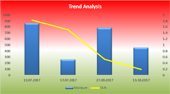
Case Study 1: A power plant in Northern India using Indo-Japanese Technology Turbine EHC System. The Power plant shows their awareness towards Lubrication Reliability through Reclamation of oil and with their proactiveness, managed to save the downtime values of 1.05 CR approx. Below the graph is a trend analysis of tracked parameter:
Case Study 2: India's first and largest supercritical coal-fired power plant in the private sector. This company avoided the breakdown of the Power Plant by following practices of reconditioning of oil. The below graphs show the trend analysis of TAN and NAS values tracked during the recondition of EH oil at Unit #1 and Unit #2 where Moisture level was also tracked & kept within the permissible limit.
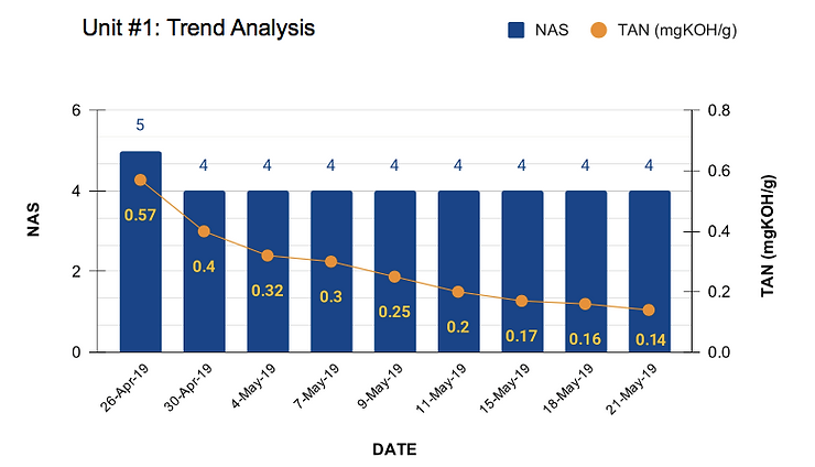
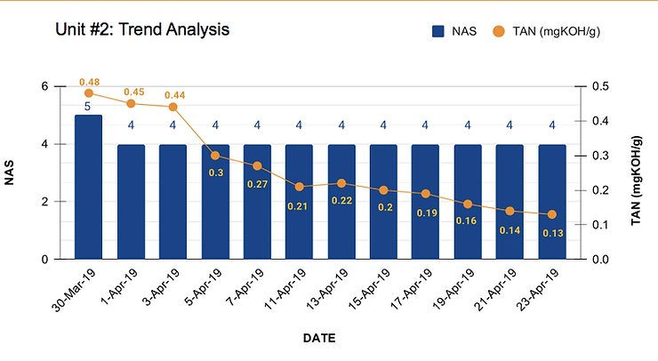
Read in detail - Article
Case Study 3: A power plant in the coastal region of India was facing a high increase in the TAN, Moisture and ISO/ NAS due to which the plant has also faced breakdown and loss in power generation. To control the values in the permissible limits, an external Reconditioning system was equipped followed by a proper oil analysis program.
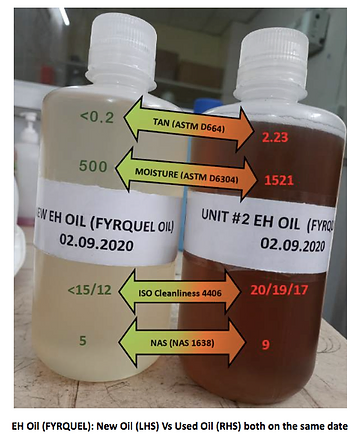
The below chart is showing the trend of a decrease in the values with continuous cycling of EH Oil.
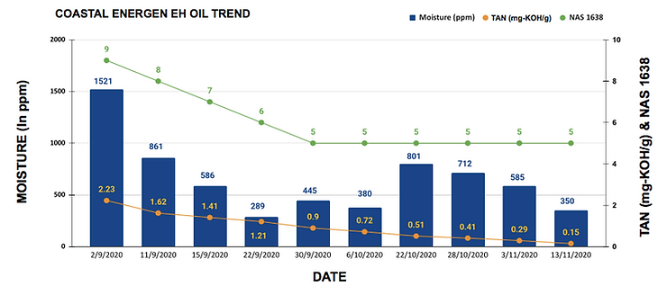
Read the full Article
Conclusion:
The performance of Hydraulic system plays a vital role in the power generation and for its high-performance many factors must be considered importantly like understanding the valve design, setting & maintaining cleanliness objective, regular monitoring, the adaption of effective purification or filtration methods, monitoring of filter quality and replacement elements etc. Good filtration will always give the lowest machine running cost and greatest reliability for the end-user of hydraulic systems. Below are the major benefits of reconditioning of oil:
- Extend oil life
- Increased machine reliability
- Reduced environmental contamination
- Cost-saving on oils replacement
- Time and effort saved for oil change out
- Decreased waste disposal cost
- Low carbon emission
- Sustainable development
Call +91 7030901267 & speak to our Technical Experts and save Maintenance Cost.
Author: Mr Yogesh Kumar is a Mechanical Engineer with vast working experience of 11 years in Power plants. He has completed PGDC in Thermal Power Plant Engineering from NPTI. He is a certified Machinery Lubrication Analysis (MLA II) from the International Council of Machinery Lubrication (ICML), Vibration Analyst Level II from MOBIUS Australia, ISNT certified NDT Level II professional in RT, UT, DPT, MPI, BOE (Boiler Operation Engineer) Certification.
Co-Author: Ms Preeti Prasad is a Chemical Engineer with working experience in Refinery and various other sectors in connection with Lubrication Consultancy. She is a certified Machinery Lubrication Technician (MTL I) from the International Council of Machinery Lubrication (ICML).
Reference Taken:
- Contamination Control - A Hydraulic OEM Perspective: Workshop on Total Contamination Control Centre for Machine Condition Monitoring Monash University, August 1997.
- ASTM Paper on IX treatment, Whitepapers on Phosphate Ester from EPT clean
- National Power Training Institute
- Other documents from Scribd.com
Share this on